
 English
 русский
 Español
 عربى
عربى





Industry Knowledge
The Physics Behind Noise Reduction Buffer Material: Absorption, Damping, and Isolation Are Not the Same Thing
A frequent source of specification errors in engineering and procurement is conflating three acoustically distinct mechanisms under the single phrase "noise reduction." Each mechanism operates on different physical principles, requires different material structures, and addresses different noise transmission paths. Understanding the difference is the prerequisite for selecting effective Noise Reduction Buffer Material for any specific application.
- Sound absorption converts airborne acoustic energy into heat through internal friction within a porous or fibrous medium. Open-cell polyurethane foam and mineral fiber materials excel here. Effectiveness is frequency-dependent: absorption coefficients are high above 500 Hz but drop sharply at low frequencies unless material thickness is increased significantly — typically to one-quarter the wavelength of the target frequency.
- Vibration damping dissipates structural vibration energy within a solid component before it radiates as airborne noise. Viscoelastic materials — including constrained-layer damping composites and damping foil tapes — are the functional solution. The loss factor (η), typically ranging from 0.1 to over 1.0 for high-performance damping materials, quantifies this energy dissipation capacity.
- Vibration isolation physically decouples a vibrating source from adjacent structures using compliant buffer elements — rubber mounts, foam gaskets, or elastomeric pads. Isolation efficiency depends on the ratio of excitation frequency to the natural frequency of the isolation system; a ratio greater than √2 is required before any attenuation begins.
Many high-performance buffer systems combine all three mechanisms in a single laminate construction: a porous absorber layer handles airborne noise, a viscoelastic damping layer addresses structural resonance, and a compliant base layer provides mechanical decoupling. Anhui Yanhe New Material Co., Ltd., with its advanced new material research and development technologies and collaboration with universities and scientific research institutions at home and abroad, develops multi-functional buffer constructions where each layer is engineered to its specific acoustical role rather than relying on a single material to perform all three functions simultaneously.
Loss Factor and Storage Modulus: The Two Numbers That Define Damping Material Performance
When evaluating viscoelastic Noise Reduction Buffer Material for structural damping applications, two dynamic mechanical properties determine whether a material will perform adequately in service: the loss factor (η) and the storage modulus (E'). These values are not constants — they vary significantly with temperature and frequency, which is why data sheets that list only a single-temperature damping value are insufficient for real engineering decisions.
The storage modulus describes the elastic (energy-storing) component of the material response. A material with too high a storage modulus becomes too stiff to deform under the strains induced by structural vibration, limiting energy dissipation. A material with too low a storage modulus may conform well but lacks the mechanical coupling necessary to extract energy from the vibrating substrate. The optimal E' range for constrained-layer damping applications is typically between 1 MPa and 100 MPa at the operating temperature.
The loss factor represents the ratio of energy dissipated per cycle to energy stored per cycle. For reference:
| Material Type | Typical Loss Factor (η) | Temperature Sensitivity | Effective Frequency Range |
| Steel (structural reference) | 0.001–0.003 | Very low | Broadband |
| Natural rubber | 0.05–0.15 | Moderate | Low to mid |
| Polyurethane foam | 0.1–0.3 | Moderate–high | Mid to high |
| Viscoelastic damping polymer | 0.5–1.5 | High — peaks near Tg | Narrow unless formulated |
| Constrained-layer composite | 0.2–0.8 (system-level) | Moderate | Broadband |
Because viscoelastic damping polymers exhibit their peak loss factor near the glass transition temperature (Tg), formulating a material whose Tg aligns with the intended service temperature range is critical. For an automotive interior application at 20–80°C, the damping polymer must be formulated differently than one intended for electronics operating at –10°C to 60°C. As a China Label Material Manufacturers and specialty material developer, Anhui Yanhe New Material Co., Ltd. applies customized formulation strategies to target the specific operating temperature window of each customer's application.
Noise Reduction in Consumer Electronics: Where Buffer Material Design Becomes Precision Engineering
Consumer electronics present a uniquely demanding set of constraints for Noise Reduction Buffer Material: the available installation space is measured in fractions of a millimeter, operating temperatures cycle repeatedly, assembly processes involve automated placement at high speeds, and end users perceive any acoustic anomaly — rattle, buzz, or click — as a quality defect. The noise sources within consumer electronics enclosures are also varied, requiring different buffer solutions to coexist within a single device.
Primary Noise Sources and Corresponding Buffer Strategies in Electronics
- Fan and motor vibration — low-frequency structural vibration (typically 20–200 Hz) transmitted through mounting points. Addressed with compliant rubber or microcellular urethane gaskets at the mounting interface. The buffer material must have a natural frequency below the motor operating frequency range to achieve effective isolation.
- Component rattle — loose mechanical clearances between PCB components, connectors, or housings excited by external vibration. Buffer foams or die-cut elastomeric pads fill gaps and constrain relative motion without adding excessive mass or stiffness to the assembly.
- Coil whine — high-frequency electromagnetic excitation of inductors and transformers (typically 1–20 kHz) causing the coil structure to vibrate and radiate noise. Potting compounds or constrained-layer damping applied directly to the coil body reduce vibration amplitude at the source.
- Screen and housing resonance — flat panel displays and thin metal housings have natural resonant frequencies that amplify specific audio frequencies. Viscoelastic damping tape laminated to the reverse of display panels or housing sections raises the structural damping ratio and reduces peak resonant amplitude.
- Hard drive and optical drive mechanisms — rotational imbalance and seek-mechanism impulses generate broadband noise. Multi-layer buffer constructions combining rubber isolation mounts with foam absorbers in the drive bay provide both isolation and residual airborne noise attenuation.
Thickness constraints in compact devices often limit buffer material selection to products under 1 mm. Ultra-thin microcellular foams and adhesive-coated damping films manufactured to caliper tolerances of ±0.05 mm are the only viable options for smartphone, tablet, and laptop assemblies, requiring precision coating and converting capabilities beyond those of general-purpose foam fabricators.
Functional Tape Constructions for NVH Control: How Adhesive and Buffer Layer Work Together
In noise, vibration, and harshness (NVH) management applications, functional tapes for the electronics industry that integrate a buffer or damping layer with a pressure-sensitive adhesive offer a significant assembly advantage over separately installed components. The tape construction eliminates the need for mechanical fasteners, allows precise placement, and ensures consistent compression on the buffer layer across automated production volumes. However, the co-engineering of the adhesive and buffer layers — rather than treating them as independent selections — is what determines whether the composite tape performs to specification.
The adhesive layer in a noise reduction tape must satisfy conflicting demands: sufficient tack and peel strength to maintain bond integrity under thermal cycling and vibration, while remaining compliant enough not to rigidly couple the surfaces it joins — which would reduce isolation effectiveness. A high-modulus structural adhesive bonded between a vibrating panel and a chassis will transmit vibration efficiently; the same joint made with a compliant viscoelastic adhesive will attenuate transmission while maintaining adequate bond strength for most electronics assembly applications.
Common Multi-Layer Noise Reduction Tape Constructions
- Foam + single-sided PSA — the simplest construction. Die-cut foam buffer pads with adhesive on one face, used for gap-filling, rattle prevention, and light vibration isolation. PET foam and EPDM foam are common substrate options.
- Viscoelastic polymer + constraining foil + PSA — a constrained-layer damping tape. The viscoelastic layer is bonded between a rigid aluminum or PET foil constraining layer and the adhesive, which bonds to the vibrating substrate. Shear strain in the viscoelastic layer during flexural vibration dissipates energy. Effective for panel damping on enclosures, appliance panels, and structural sheet metal components.
- Dense rubber layer + foam layer + double-sided PSA — a composite construction combining mass (from the dense rubber layer), absorption (from the foam layer), and adhesive bonding on both surfaces. Used in automotive and HVAC applications where both structure-borne and airborne noise paths are active simultaneously.
- Silicone foam + high-temperature PSA — for electronics applications near heat sources such as power electronics and LED modules. Silicone foam maintains its compression recovery and buffer performance above 150°C where polyurethane foams would begin to degrade.
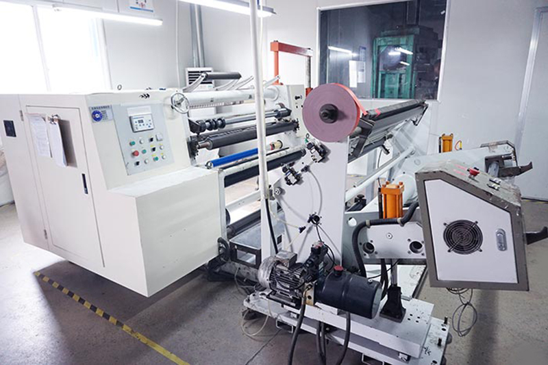
Founded in 2012 and operating on a 17-acre production site in Guangde Economic Development Zone West, Anhui Yanhe New Material Co., Ltd. develops adhesive products for various functional film materials with the converting capability to produce these multi-layer constructions to customer-specified dimensions, including narrow-slit tape formats compatible with automated dispensing systems used in high-volume electronics manufacturing.
Material Selection Variables Specific to Automotive NVH Buffer Applications
Automotive NVH (noise, vibration, and harshness) applications impose a set of performance requirements that are more demanding than most industrial or consumer electronics contexts. Buffer materials installed in vehicle cabins, door panels, floor systems, and engine compartment barriers must simultaneously maintain performance across a temperature range of approximately –40°C to 120°C in cabin areas and up to 200°C near engine components, resist long-term compression set, comply with flammability standards (FMVSS 302 or equivalent), and survive the full vehicle service life without degradation in acoustic performance.
Compression set is a particularly critical failure mode for automotive buffer materials. A foam or elastomeric buffer installed under sustained compressive load — such as a door seal, floor mat stiffener, or component mounting pad — will permanently deform over time if its compression set resistance is insufficient, reducing the effective contact force and diminishing isolation or damping performance. PORON microcellular urethane and silicone foam families are preferred in applications requiring low compression set over multi-year service lives, with compression set values below 10% after 22 hours at 70°C in many engineering-grade formulations.
Additional selection parameters specific to automotive applications include:
- Fluid resistance — buffer materials in underhood or underbody locations may contact fuels, engine oils, transmission fluids, and road salts. EPDM and silicone elastomers offer the broadest chemical resistance profiles; open-cell polyurethane foams absorb fluids and are unsuitable for exposed underbody use.
- Fogging resistance — volatile compounds from foam materials that condense on interior glass surfaces represent a regulatory and quality concern. Automotive interior specifications typically require fogging values below 1.0 mg per DIN 75201 methodology.
- Weight constraints — vehicle mass reduction requirements push buffer material selection toward the lowest density option that still meets acoustic performance targets. Micro-porous structures with densities below 100 kg/m³ are increasingly specified over heavier rubber-based damping sheets.
- VOC emissions — in-cabin buffer materials must meet OEM-specific VOC limits (typically specified as total carbon emissions in µg/m³ under standardized chamber test conditions) to comply with interior air quality requirements in major automotive markets.
Custom Noise Reduction Buffer Material Development: What the Specification Process Should Cover
Procuring a standard catalog foam or rubber sheet for a noise reduction application is straightforward; developing a custom-formulated or custom-constructed Noise Reduction Buffer Material to solve a specific, validated acoustic problem is a materially different engineering process. As a Label Material Factory with full customized manufacturing capabilities, Anhui Yanhe New Material Co., Ltd. approaches custom buffer material development through a structured specification framework that covers the complete chain from acoustic problem definition to material qualification.
A complete custom buffer material specification should address the following dimensions:
| Specification Dimension | Parameters to Define | Common Gaps in Customer Briefs |
| Noise Source Characterization | Frequency range, SPL levels, transmission path (airborne vs. structure-borne) | Specifying only "vibration" without frequency data makes material selection arbitrary |
| Installation Envelope | Maximum thickness, available area, compression gap, surface geometry | Omitting compression gap data leads to under- or over-specified material density |
| Environmental Conditions | Temperature range (continuous + peak), humidity, chemical exposure, UV | Specifying room-temperature performance only for an outdoor application |
| Assembly Process Requirements | Manual vs. automated placement, liner release force, dispensing format (roll/sheet/die-cut) | Ignoring liner specifications for robotic pick-and-place compatibility |
| Performance Validation | Accepted test method (insertion loss, transmission loss, damping ratio), pass/fail criteria | No defined acceptance criteria, making qualification open-ended |
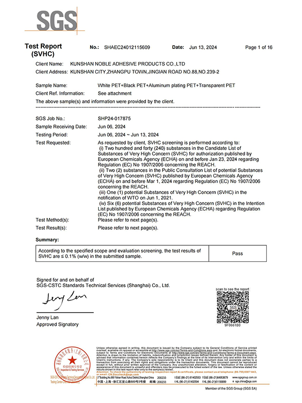
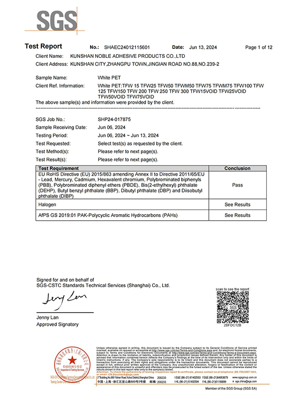
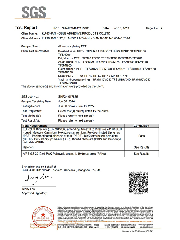
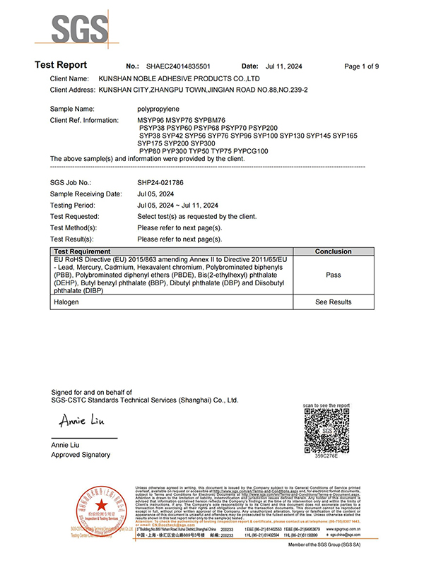
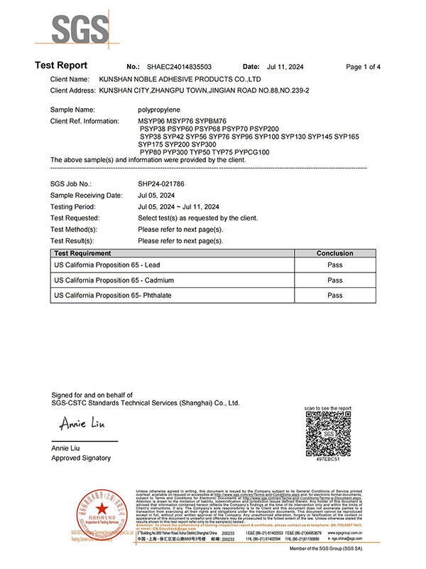
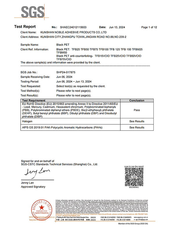
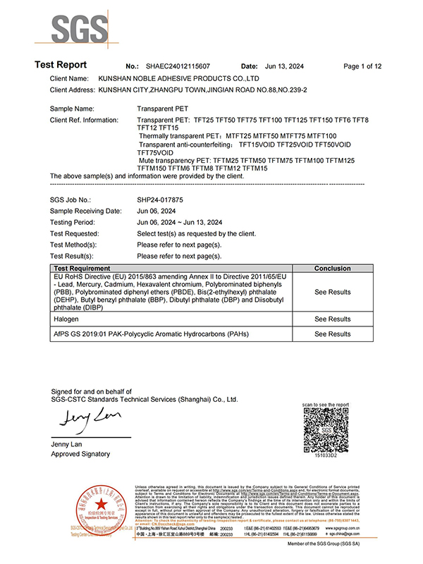
| Regulatory and Compliance | RoHS, REACH, halogen-free, flammability rating (UL94, FMVSS 302), food contact if applicable | Compliance requirements added late in development, requiring material reformulation |
By applying corresponding surface coatings based on the functional requirements of customers' different surfaces, Anhui Yanhe New Material Co., Ltd. is able to fine-tune how a buffer material interfaces with its installation substrate — adjusting adhesion level, conformability, and surface texture to match the specific assembly and performance conditions defined in the customer specification. This integrated approach to custom buffer development, supported by the company's collaborative relationships with academic and research institutions, enables systematic material optimization rather than trial-and-error sample substitution.
